Intro
All combat robots have one thing in common they all use electric motors. Motors are used to drive the robot around and in many cases power the weapon, so in order to be able to build a combat robot you need to be able to control motors. This little tutorial will show you how you can control a motor using your raspberry pi.
Firstly you need a few in-expensive parts in addition to your Raspberry pi, you will need a cheep speed controller, a cheep motor, a electrical choc block , and some jumper wires, and a power supply.
We are going to look at driving a brushless motor (however the process is more or less the same for brushed motors).
Speed Controller

To driver the motor we need to connect the motor to a electronic speed controller (ESC), the speed controller is then connected to a power supply and the Raspberry Pi. The job of the speed controller is control the power going from the power supply to the motor. The speed controller manages how much power gets to the motor and the timing of that power, thus controlling how fast or slow the motor spins (and the direction).
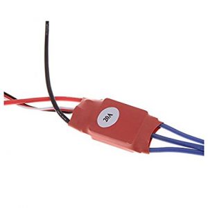
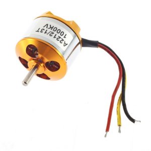
Firstly we need to connect the speed controller to the motor. This is done by connecting the 3 blue wires coming out of the speed controller to the 3 wires on the motor (red, yellow, and black) using the choc block. The order they are connected does not matter.
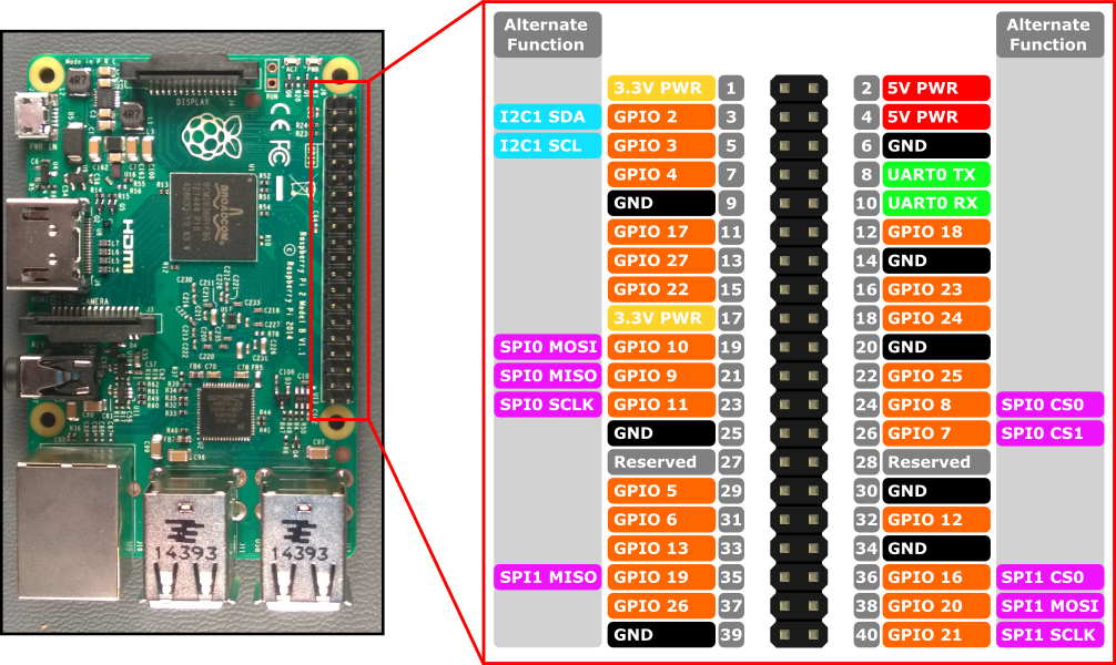
Secondly we need to connect the Raspberry pi to the speed controller. Care needs to be taken when doing this next part that you only connect the correct pins. One wire connects the Pi to the speed controller, this is done using a jumper wire to connect pin 7 (GPIO4) on the Pi to the PWM input (the white wire) on the speed controller. There is a small 3 pin connector sticking out of the the speed controller on some wires, it’s the white wire on this connector that is the PWM input. The red and black wires on the small 3 pin connector the battery elimination circuit (or BEC as its otherwise know). The BEC provides power from the speed controller that we don’t need, infact connecting it to the GPIO pin of the Pi would blow that GPIO line which would be bad, so please double check pin 7 on the Pi only connects to the white wire.
Setting up the Pi
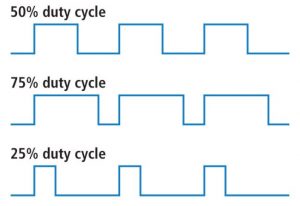
Now almost all the wiring is done (except for power we will do this last) we will look at getting the Pi to control stuff. When connecting up the Pi to the speed controller we mentioned the PWM pin. PWM stands for pulse width modulation, and its one of the standard techniques for getting digital electronics to control stuff. The way it works is by sending a timed electric pulse. Lets say we are expected to send a pulse every 1 millisecond, if the pin sending the pulse is on for 50% of the 1ms and off for the rest we are sending a 0.5ms pulse. It is the length of the pulse that tells the speed controller how fast to spin the motor.
In the case of our speed controller it can only spin the motor in one direction (well it is a very cheep speed controller), so 0% means don’t spin the motor (as does 100%), 99% means spin the motor at full speed. The speed controllers we use in our robot are more expensive and can spin the motor in both directions, however the principle is the same it expects a 1ms pulse length, if it gets no pulse it does not spin the motor. The first 49% of the pulse length controls how fast in spins in one direction and the next 51% – 99% how fast the other way. A pulse length of 50% (0.5ms) tells the speed controller not to spin the motor as does 0% and 100%.
We now need some code to control our GPIO pin and switch it on/off to send the PWM signal. We are going to use the pi-blaster application for this.
Firstly we will install git so we can check out the code, and a few of the tools we need to build the code
On debian based installs

sudo apt-get install git gcc autoconf

On fedora/centos based installs

sudo yum install git gcc autoconf
We can then check out the code
git clone https://github.com/sarfata/pi-blaster.git
cd pi-blaster
We now need to build the code
./autogen.sh
./configure
make
This should compile the code, if it worked we now need to install pi-blaster
sudo make install
sudo systemctl enable pi-blaster
sudo systemctl start pi-blaster
Our software in now installed and ready.
Connecting the power
Now everything else connected and setup we are ready to connect up the power, before you do you should probably double check the connection between the pi and the speed controller is correct. If it is not, this is the moment where we can blow the pin.
Have you checked the connection between the Pi and the speed controller 🙂
When the speed controller powers up we can calibrate the pulse length used to control it, so we set our the Pi to produce the pulse length that means full speed.
echo "4=0.99" >/dev/pi-blaster
This sets GPIO4 (pin 7) to be on for 99% of the time (so on for 0.99ms for every 1ms). We then connect the power to the speed controller with the fat red cable connecting to positive and the fat black cable to negative.
You will hear 3 tones from the speed controller, meaning is picked up the pulse width for full speed. We then set the pulse width to the lowest speed.
echo "4=0.01" >/dev/pi-blaster
This sets GPIO4 (pin 7) to be on for 1% of the time (so on for 0.01ms for every 1ms). The speed controller will then play 3 notes telling us its configured.
The speed controller only needs configuring the once, in the future we can just connect the power and it will remember the settings.
You can now turn the PWM signal off.
echo "4=0" >/dev/pi-blaster
Using it
Now everything is connected and configured we can now set the motor to what ever speed we want. All we have todo is pick a value from 0 to 0.99, the closer the value is to 0.99 the faster it goes. Setting it to 1 should cause the motor to stop as should setting it to 0.
#Quarter speed
echo "4=0.25" >/dev/pi-blaster
This method can be used to write small programs to control the motor. So for example if you create a file called motor.sh containing the contents below.
#!/bin/bash
echo "4=0.25" >/dev/pi-blaster
sleep 10
echo "4=0.50" >/dev/pi-blaster
sleep 10
echo "4=0.0" >/dev/pi-blaster
Then you can run it and it will set motor to quarter power, then wait 10 seconds, then set it to half power, then after 10 seconds turn off.
chmod u+x motor.sh
./motor.sh
How does this differ from the real thing ?
Basically there is very little difference between what you have set up here and how we drive our robot. We use a more expensive speed controller that can spin the motor is both directions, and there is more than one speed controller.
Our robot uses a Raspberry Pi to control the speed controllers just like in this tutorial, and for each speed controller we use a GPIO pin to send the PWM signal to the speed controller. While we don’t use pi-blaster to control the pins, our software uses the same technique to control the pins its just directly built in. This is a safety measure in case the main control program dies, so the pins stop producing the PWM signals. Thus the speed controllers shutdown the motors, and the robot does not run round out of control. We also have also added a bit of electrical protection around the GPIO pins so if something shorts or power ends up in the wrong place the Pi does not get killed. This is because we expect to take alot of impact shock from other robots trying to destroy our robot.